IMU filtering on an STM32 + MPU6000
#hardwareFor making balancing robots (disclaimer: not my robot), you certainly need a good sense of the robot’s orientation in the world. I had a disastrous experience a few months ago of trying to use a $1500+ IMU which breaks if your robot moves too fast. Like, 300 degrees/sec, which is nothing for a relatively small, agile robot.
After that fiasco was remedied by inventing the World’s Stupidest IMU™—a laser-cut pulley and rubber band device that surely deserves a post for itself—I decided to upgrade from the $1500 sensor to a $5 MPU6000.
This meant doing the filtering on a microcontroller, which was an exciting prospect with the DSP/FPU hardware on the STM32F373 I’ve been using.
Math libraries
The CMSIS DSP libraries have special Cortex-M4 functions like fast trigonometric, FFT and matrix functions, but thankfully, some testing showed that embedded Eigen does matrix multiplies and inverses just as fast as the CMSIS DSP functions (at least, with -O3 -ffast-math), meaning I could use the more convenient syntax without fear of being slow.
Filtering
The IMU combines an accelerometer (which intuitively tells you—only if the robot is moving very slowly—which direction gravity is, using which you can back out the orientation):
\[\widehat r_{\mathrm{acc}} = \tan^{-1} (a_x, a_z) , ~~~~~ \widehat p_{\mathrm{acc}} = -\tan^{-1} (a_y, a_z)\]and a (rate) gyroscope whose readings can be integrated to also have a horribly drifty estimate of orientation. There are numerous articles online which describe how the CF makes the best of high-frequency and low-frequency responses of the gyroscope and accelerometer, but the way in which they are combined
\[\widehat r = \lambda \widehat r_{\mathrm{acc}} + (1 - \lambda) \widehat r_{\mathrm{gyro}}\]should make anyone uneasy. The roll and pitch don’t lie on a linear space, and this addition to interpolate doesn’t make much sense. The quaternion-EKF which I adopted from Gareth Cross solves two of the problems with the CF by
- switching to a non-singular representation (quaternions), and
- using a more principled filtering technique (intuitively keeping track of a belief over the best state to explain the measurements, versus ad-hoc combining the disparate state estimates).
Experiments
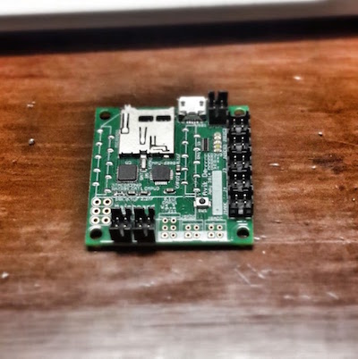
I did the experiments on one of my own “mainboards” (boards that basically have all the things I think I’ll need so I don’t have to make a new one for every project):

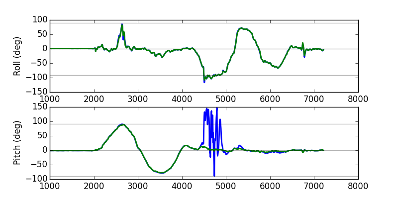
For each of the plots, the blue trace is the complementary filter and the green trace is the EKF. I sort of tuned them both to have similar squiggliness (that’s the statistically correct way to do this, right?) in this “control” test:
Slow movements—pitch followed by roll
I moved the board back and forth first about the pitch axis, then the roll axis:

The results here are as expected, and already we see that the EKF’s use of a singularity-free representation means that it can avoid the complementary filter’s pitch estimate mishap at ~90 degrees of roll.
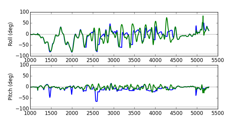
Rapid motions
Things get more interesting here, and (while there’s no ground truth here–sorry on vacation–you’ll just have to believe that I was spinning the board back and forth at ~6 Hz) it looks like the CF “gives up” at times where the EKF is still tracking the oscillations.

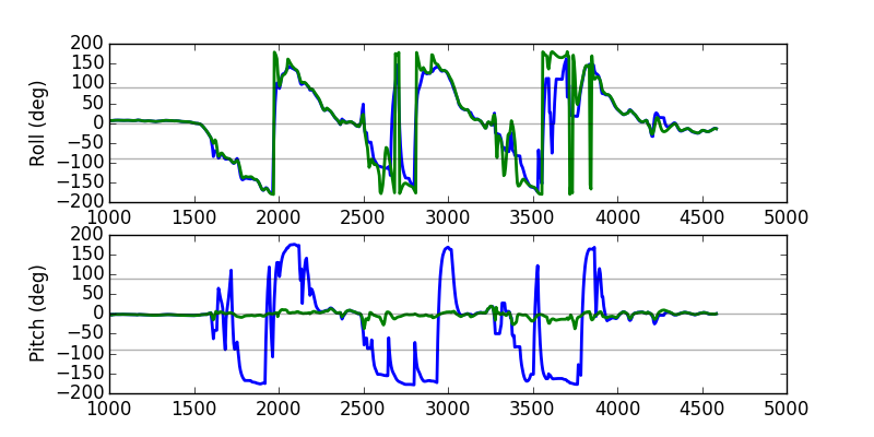
Three full rotations in roll
The last test I did was just do 3 full rotations in roll, and while the roll traces look OK (there’s some nonsense and jittering happening around the wrap-around because I insisted that the quaternion be converted back to an euler angle) the pitch on the CF is very mysterious indeed. It keeps jumping from 0 to \(\pm\pi\)!

Timing results
Other than the evidence that the EKF’s estimate itself is superior, the last important matter is the computation time (see below for the full code):
// Print computation time in us
Serial1 << "Read:" << tic1 << "\tCF:" << tic2 << "\tEKF:" << tic3 << endl;
// PRINTS: "Read:44 CF:16 EKF:119"
Thanks, SPI and hardware floating-point! This means that it should be possible to do closed-loop feedback control at almost 5 KHz even with the EKF!
Now to actually use this on the robots…
Code
The entire code to do this experiment (using the koduino libraries) is:
#include <Eigen.h>
#include <SPI.h>
#include <MPU6000.h>
#include <ComplementaryFilter.h>
#include <EKF.h>

const int led = PC13;
MPU6000 mpu;
ComplementaryFilter cfilt;
EKF ekf;

void setup() {
  // pinMode(led, OUTPUT);
  Serial1.begin(115200);

  // SPI connection pins - should these be fixed?
  SPI.setPins(PA12, 6, PA13, 6, PF6, 5);
  if (!mpu.init(PC15)) {
    while (1) {
      Serial1 << "WHO_AM_I did not match" << endl;
      delay(1000);
    }
  }

  // Set params here
  cfilt.dt = 0.001;
  cfilt.smooth = 0.7;
  cfilt.acclb = 5;
  cfilt.accub = 20;
  cfilt.flipz = false;

  // Start off the EKF
  mpu.readSensors();
  ekf.init(mpu.acc);
}

void loop() {
  uint32_t tic1 = micros();
  mpu.readSensors();
  tic1 = micros() - tic1;

  uint32_t tic2 = micros();
  cfilt.update(mpu.acc, mpu.gyr);
  tic2 = micros() - tic2;

  uint32_t tic3 = micros();
  ekf.update(mpu.acc, mpu.gyr);
  tic3 = micros() - tic3;

  const EulerState *e = cfilt.getEuler();
  const EulerState *ekfe = ekf.getEuler();

  // Read:44  CF:16 EKF:119
  Serial1 << "Read:" << tic1 << "\tCF:" << tic2 << "\tEKF:" << tic3 << endl;

  Serial1 << "[" << millis() << "," <<
    degrees(e->angles[0]) << "," <<
    degrees(ekfe->angles[0]) << "," <<
    degrees(e->angles[1]) << "," <<
    degrees(ekfe->angles[1]) << "],\n";

  delay(5);
}